#statusMessage#
Do you want to start the compare now?
#statusMessage#
Do you want to start the compare now?

Our electromagnetic environment is heavily burdened due to the multitude of transmitters and sources of interference pre...

Automated test and measurement systems that are fully connected with instrumentation and test data can significantly inc...

Temperature is one of the most common risk factors in industry. Overheating can disrupt processes, reduce quality or cau...

Electric vehicles are the future - but what happens to the batteries when they can no longer be used in cars? Efficient ...

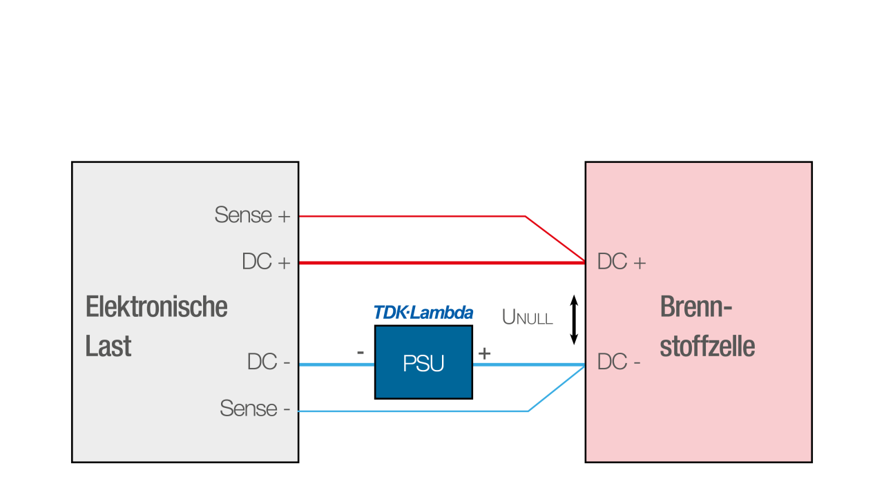
Due to an unavoidable minimum internal resistance - the so-called RDS(on) (minimum on-resistance of the FET between drain and source) of the integrated power semiconductors - electronic loads have a certain minimum input voltage UMin. According to Ohm's law, a load can only draw the full rated current above this voltage. Below the minimum voltage, the maximum current that can be drawn decreases linearly. In order to utilise an electronic load below the UMin limit with full rated current, an additional external DC power supply unit can be used to compensate for the minimum voltage of the load (see illustration).
The external DC power supply unit (PSU) is connected in series to the DUT in the DC minus line. Through the sense line, which is connected directly to the test object, the electronic load displays the voltage measured on the test object and ensures correct regulation in the constant voltage CV and constant resistance CR operating modes.
The nominal voltage of the external power supply unit can either be variably adjustable or fixed. It should be as low as possible, i.e. no more than 5 % of the rated voltage of the electronic load. It is therefore sufficient if the voltage is slightly higher than UMin of the load. At the same time, the power supply unit must be able to supply at least as much current as the device under test.
In this test setup theGSP10-1000-3P by TDK-Lambda Germany is used. With 10 V and 1,000 A, it is ideally suited in this setup as an external DC power supply unit (PSU), which is set between 1 V and 4 V; 4 V would correspond to 5 % of the 80 V nominal voltage of the electronic load.

Abb.: TDK-Lambda GSP10-1000-3P GENESYS+ DC-Netzgerät
A fuel cell should be loaded so heavily that its output voltage drops to 0 V. Taking into account the type-specific internal resistance of the fuel cell, this requires the internal resistance of the electronic load to be lower or its conductivity to be greater than that of the fuel cell. The electronic load should ultimately have an internal resistance of 0 Ω. This can be remedied by an additional external DC source that compensates for the voltage drop at the internal resistance of the electronic load.
Die Brennstoffzelle stellt den Prüfling dar (DUT, Device under Test), deren Ausgangsspannungskennlinie typischerweise zwischen 0 V (Kurzschlussstrom Isc) und 1 V (reale Leerlaufspannung Uoc) liegt. Der Arbeitsbereich beträgt, je nach Brennstoffzellentyp, zwischen 0,3 V und 0,8 V. Technisch bedingt erfordert die Last eine Mindestspannung UMin von 0,66 V am DC-Eingang, damit sie die 1.000 A Nennstrom vollständig aufnehmen kann. Die Zellenspannung des Prüflings ist somit niedriger als die der elektronischen Last.
Die elektronische Last wird zunächst auf 0 V, volle Leistung sowie einen beliebigen Strom eingestellt, der noch im typischen Spannungsbereich des Prüflings liegt. Das externe DC-Netzgerät sollte eine regelbare Stromgrenze besitzen und wird auf 1.000 A eingestellt. Nach dem Einschalten des DC-Ausgangs am Netzgerät sowie des DC-Eingangs der Last nimmt diese zunächst den eingestellten Strom aus der Brennstoffzelle auf. Anschließend wird der Strom der Last kontinuierlich erhöht, während die Zellenspannung bis hinunter auf 0 V einbricht. Sobald die Last in den CV-Betrieb (Konstantspannung) wechselt, ist die Stromlieferfähigkeit der Zelle bei 0 V ermittelt.
Die komplette GENESYS+ Serie

