#statusMessage#
Do you want to start the comparison now?


Without reliable communication, safe operation is impossible. In the aerospace industry, failures are not an option. At ...

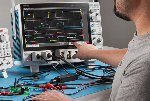
In safety-critical development and manufacturing processes, the test architecture determines quality, cost efficiency, a...

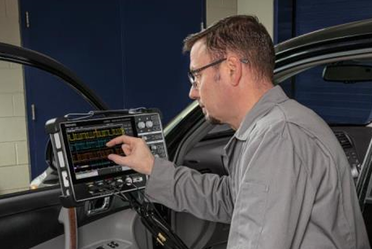
Increasing efficiency requirements in vehicles, data centers, and industry are driving new vehicle electrical system and...

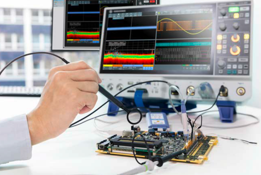
Early prevention, comprehensive certification, targeted troubleshooting. In every area of your data center, measuring in...
Manufacturer number: CT1


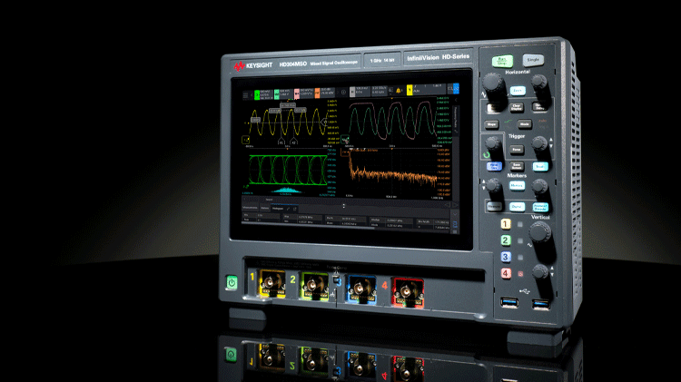
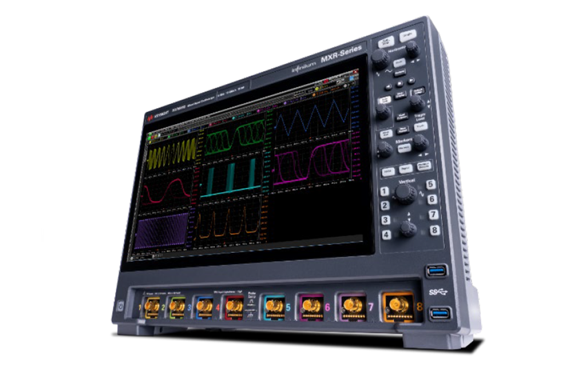
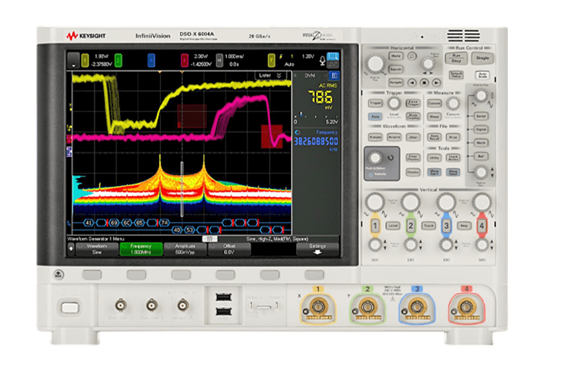
Tektronix is a global leader in test, measurement, and monitoring solutions for applications in aerospace, education, automotive, and telecommunications. The portfolio includes oscilloscopes, arbitrary/function generators, spectrum analyzers, and signal generators, as well as product segments from EA Elektro-Automatik and Keithley.
.webp "Seminar LabVIEW Core 1")