#statusMessage#
Do you want to start the compare now?


With the increasing importance of renewable energies in the wake of climate change, solar energy is moving further into ...

The complexity of military radios and the often harsh weather conditions have a negative impact on the reliability of ra...
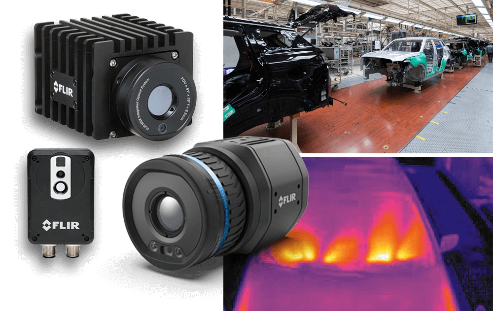
Automation with thermal imaging technology has proven to be a reliable solution for quality control in various industrie...

In diesem exklusiven Whitepaper erfahren Sie, wie Sie mit der richtigen Messtechnik arbeiten: ✔ Sie realisieren ein Test...
Immerse yourself in the world of probes and deepen your knowledge. Our experts are ready to shed light on all facets of the use of oscilloscope probes with you.
Some questions can be answered easily and directly on the phone. Just call us. Our experts will be happy to assist you.
