#statusMessage#
Do you want to start the comparison now?


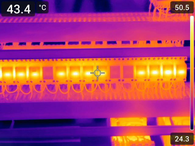
How Thermography Enhances Manufacturing. Machine stoppages, component overheating, or electrical faults—unplanned downti...

Disturbances in the power grid often go unnoticed until systems shut down or equipment fails. Regular power quality asse...

In this practical checklist you will learn how to calibrate your measuring and test instruments effectively – simply, ef...
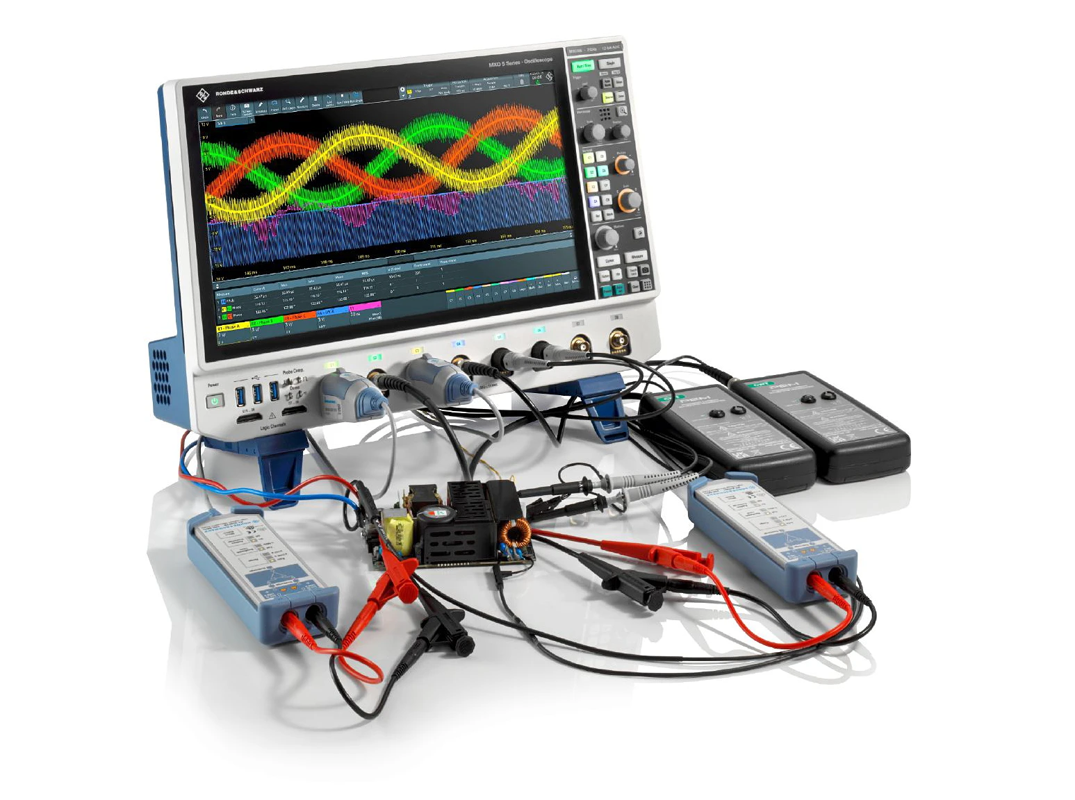
Modern oscilloscopes of the MXO Series from Rohde & Schwarz enable precise analysis and optimization of electric dri...
Experience the versatile possibilities of signal generation with the signal generator. Our experts will help you discover all aspects of the use and application of this powerful tool and deepen your knowledge. Get an overview of our product range.
Some questions can be answered easily and directly on the phone. Just call us. Our experts will be happy to assist you.

