#statusMessage#
Do you want to start the comparison now?


In this practical checklist you will learn how to calibrate your measuring and test instruments effectively – simply, ef...
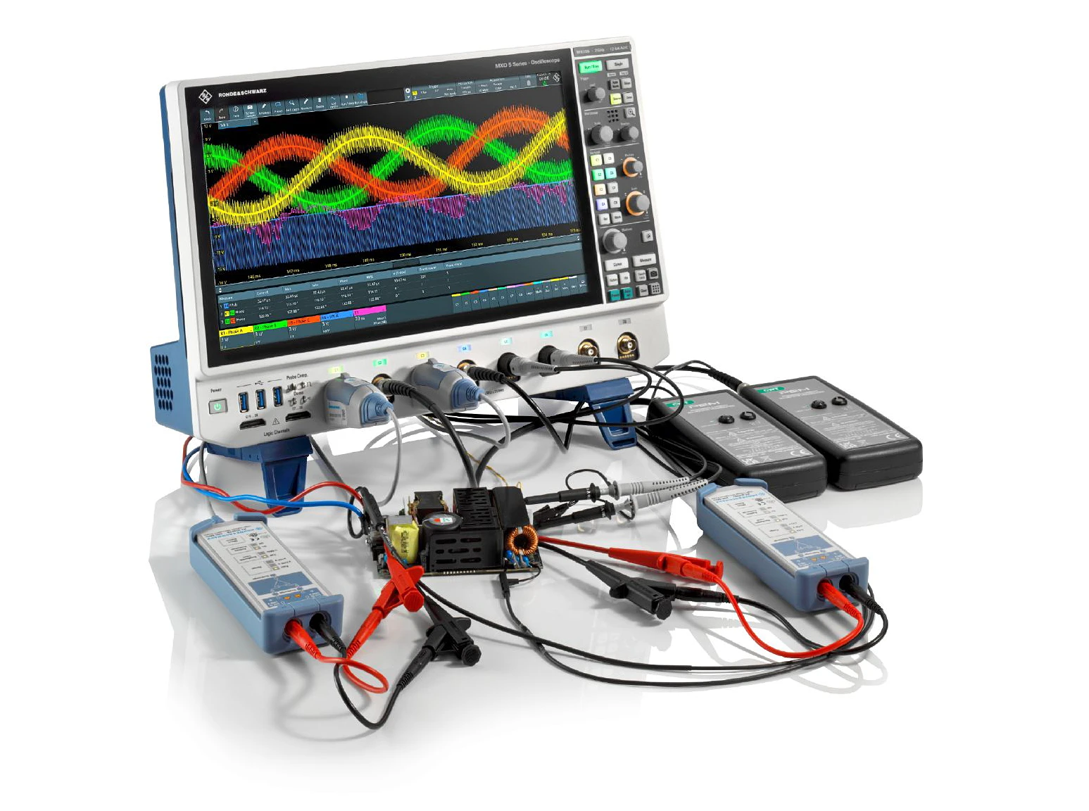
Modern oscilloscopes of the MXO Series from Rohde & Schwarz enable precise analysis and optimization of electric dri...
There is a trend in all sectors towards products with as many functions as possible. The more features a product has, the more complex test development becomes. At the same time, tight schedules and project deadlines for the market launch have to be met. A precise and fast data acquisition system (DAQ) can help you meet this challenge. But what are the right components and settings for optimizing this type of test system?
The measurement accuracy and speed of a data logger influence both the quality and the throughput of a test environment. The right choice of test components and parameters helps to optimize test development. This guide gives you an insight into how data acquisition works with a data logger. The guide focuses on the:
A data acquisition system (data logger) collects measurement data with the aim of characterizing, monitoring or controlling a product or process. Measurement data is acquired over a defined period of time; several physical measured variables can be recorded, saved and displayed graphically or numerically at the same time. The measurement data is recorded simultaneously or sequentially, digitized and stored internally or transferred to an externally connected memory for further data analysis. Special sensors convert e.g. temperature, voltage, current, resistance, frequency or pressure into an electrical signal voltage. DAQ systems are used, for example, for maintenance, fault diagnosis or performance analysis.
During product characterization, various input parameters such as voltage and current must be measured or the temperature recorded at several points simultaneously. Test development includes the optimization of measurement accuracy and measurement speed.
When monitoring a product or process, for example, regular measurements are taken every minute for several hours. This includes pre-processing or calculating the data during recording in order to analyze it afterwards. External monitoring devices such as alarm lights or warning tones are often triggered in order to initiate appropriate corrective measures.
If the test process is to be controlled, for example, analog output signals must be provided to control actuators, motors, etc., or signals must be routed via a switching module to supply a device under test (DUT) with power or test signals.
The applications for a data logger are typically characterized by data acquisition over a certain period of time, by recording temperature curves and/or by checking the service life and reliability of power systems:
The measurement hardware consists of the analog, digital and counter inputs of the DAQ. The analog inputs usually record DC voltages, which are then converted into digital data via an analog-to-digital converter (ADC). The measured voltages correspond, for example, to defined temperature values or speeds.
Some DAQs have a digital module whose digital inputs can scan the bit patterns of external DUTs. Such modules usually have eight, 16 or 32 channels and can monitor several DUTs or states. For example, a control panel can be connected and the position of various switches on it can be determined. On the other hand, data loggers with a counter module can count external events such as the number of digital pulses, the pulse duration or the frequency.
Fig. 1: Typical hardware components of a data acquisition and switching system (in German)
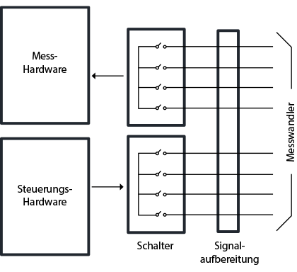
The control hardware comprises the output component of a DAQ. It essentially consists of the analog, digital and switching outputs. A digital-to-analog converter (DAC) interprets the commands from the control hardware and outputs them as DC voltages or currents. This analog output can control the position of a valve or the flow rate of a pump.
DAQ systems with a digital module convert commands into a bit pattern and control, for example, lights or other systems. A switching module, also known as an actuator, supplies the external devices with power by closing a circuit, similar to the function of a light switch. Switching modules are used instead of a digital module if a circuit requires higher voltages and powers.
The DAQ switching networks are either integrated or can be used as separate modules. The switching hardware can be used, for example, to record the measured values from sensors sequentially or synchronously. The switching blocks also act as stimuli for a DUT, for example by providing different temperature values. Electromechanical reed relays are generally used for low-speed applications. The advantage is their ability to switch high voltage and current levels.
The disadvantage is the limitation to a few hundred channels per second and the potential wear to their mechanical parts. Electronic switches such as field-effect transistors (FETs) and solid-state relays are therefore used for high-speed applications because they require no moving parts that could wear.
However, they cannot switch high voltages and currents and must have a high impedance as protection against peaks or transients. Signal conditioning hardware converts the signals from the transducer into a measurable form by amplifying, attenuating, linearizing or isolating the signals before they are sent to the measurement hardware.
Sensors convert physical parameters into an electrical signal. There are various types of such transducer: e.g. thermocouples, thermistors, rotary encoders. Sensors can be divided into passive and active sensors.
Passive sensors change their resistive, capacitive or inductive properties when their corresponding physical parameters change. They require an external power supply to generate an electrical output. A thermistor, for example, does not generate an electrical signal; it changes its resistance according to changes in temperature. If an electric current flows through its resistor, an output voltage can be measured to detect temperature fluctuations.
Active sensors generate electrical current when the physical environment changes. Examples of such sensors are thermocouples, piezoelectric and photo diodes.
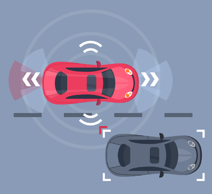
In contrast, actuators convert electrical signals into physical parameters. A data acquisition system can provide analog or digital output signals to control an actuator, regulate a temperature, control a fluid flow or trigger a movement with the help of a motor. Sensors and actuators often work together.
One example: In a motor vehicle, a sensor measures the oil level or water temperature. The data is forwarded to the vehicle computer, which analyzes the data and activates certain actuators. In cars with collision avoidance systems (CAS), the speed sensor and radar system supply data to the vehicle computer. If a collision is imminent, the actuators are activated, i.e. the brakes. (Photo: freepik.com).
Physical parameters (e.g. temperature, flow velocity, pressure) are converted into electrical signals (AC/DC voltage, current, etc.) via a sensor and forwarded to the DAQ measurement hardware. Interference signals may occur, especially if unsuitable cables or connectors are used.
Shielded twisted pair cables can effectively counteract system-induced noise by reducing crosstalk and electromagnetic interference on other wire pairs.
Electronic devices in the vicinity, such as smartphones or laptops, can also emit interference radiation and contaminate the electrical measurement signal with noise.
Differential inputs offer a better signal-to-noise ratio (SNR) compared to single-ended signaling.
They reduce electromagnetic interference and crosstalk on neighboring cables and transmit signals with very low voltages in the mV range, which are particularly susceptible to interference noise.
They also allow precise timing for digital signal transitions or switching operations.
A DAQ usually has integrated, insulated inputs (channel-to-channel or channel-to-ground). They represent a safety barrier and protect the user from excessive voltages.
Ground loops can occur in measuring systems, e.g. due to an unfavorably selected ground contact or improper connection of the measuring system. Due to their ground decoupling, insulated inputs provide a higher measurement accuracy.
The power lines of the DUT and the DAQ itself also cause noise. Some data loggers have built-in, integrating A/D converters that suppress such mains line noise using NMR.
This is done by measuring the average DC input over a certain integration time, which corresponds to an integer value of the power cycle (PLC), so that errors are averaged to approximately zero.
A/D integration time and measurement speed require a compromise: A better NMR costs speed.
If the ground of the device under test and the measuring device are connected via a common ground, ground loops can promote additional noise. The error voltage that occurs between the two ground reference points manifests itself as measurement inaccuracy. One solution is to use a large DAQ isolation resistor.
With DC ground loops and low signal strength, it also helps to keep the grounding path as short as possible. However, most low-frequency applications are disturbed by ground loops from the AC power grid. Here again, an integrating A/D converter offers a solution.
If your test environment consists of high-frequency, fast digital signals or very noisy components such as relays or motors, it is always advisable to carry out all sensitive voltage measurements via a separate ground potential.
The DAQ and the configuration should lead to the most precise measurements possible. The parameters set for resolution, noise suppression etc. in turn influence the measurement speed, which is also an important criterion for a successful test environment.
The resolution describes how many details are recorded during a measurement, i.e. how many significant measurement points are recorded per unit of time. Accuracy is a measure of how reliable the measurement results are.
A higher resolution does not per se mean higher accuracy. A 6.5-digit voltmeter with poor accuracy is no better than a 5.5-digit voltmeter with good accuracy.
The sensitivity of the measuring device describes the smallest change in the measured signal that can be detected. It depends on both the resolution and the smallest measuring range of the DAQ.
The smaller the measuring range, the smaller the signal changes that can be measured.
The measuring speed is the speed at which the analog-to-digital converter of the DAQ acquires the measurement data, i.e. the time span between the acquisitions. As the sampling speed of the ADC increases, the resolution of the measuring device decreases.
The data sheet can be used to assess whether the highest required speed of the DAQ meets your requirements for measurement resolution.
The measurement accuracy of a data logger is influenced by various components: from the sensor to the connection cable used through to the AD converter. If one of these components is faulty, this can lead to inaccurate measurement results.
Checklist: How can the measurement accuracy of a DAQ be optimized?
Application examples:
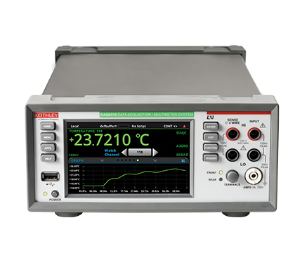
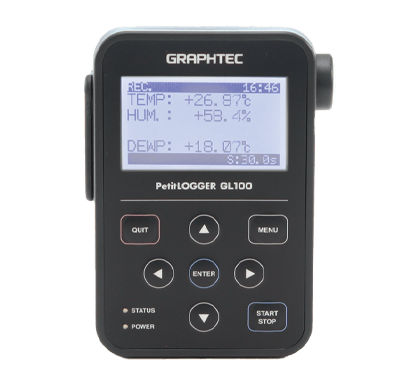
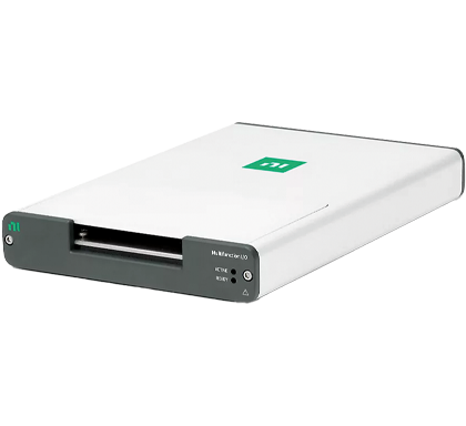
A mobile DAQ device is suitable for use in the service area, for example, if different measurement points are to be recorded and documented in different operating situations. The number of measurement points per unit of time is manageable. The measured values can be saved and processed on the PC at a later date.
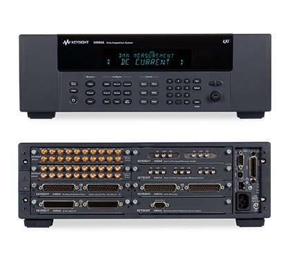
NI's PC-based data acquisition systems with plug-and-play hardware offer a particularly wide range of combination options for very flexible measurement applications. The systems are available either with a fixed range of functions or as a configurable solution. In PC-based measurement systems, the hardware is connected to your PC via USB or Ethernet: either directly - as a multifunction I/O device - or via a chassis equipped with conditioned I/O modules (CompactDAQ, CompactRIO or PXI).
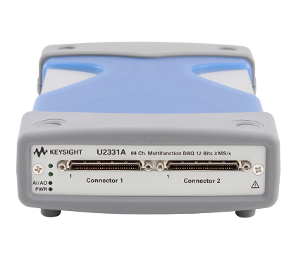
Multifunction I/O data acquisition devices are connected to a PC via USB or PCI/PCIe; they offer combinations of analog and digital inputs/outputs as well as counter/timer functions. The devices are suitable for industrial applications such as automation in the laboratory, research and design verification. The DAQExpress software included in the scope of supply provides basic measurement and analysis functions, while the NI-DAQmx driver also supplied enables the creation of user-defined automated measurement applications. The driver supports the programming interfaces of LabView, ANSI C, Python, Visual C# .NET, Visual Basic .NET and MathWorks MATLAB.
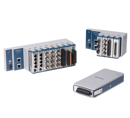
CompactDAQ systems can be optimally adapted to individual test requirements and offer a direct sensor connection. They are suitable for DAQ applications with a wide range of measurement parameters that require scalability and flexibility. Due to the robustness of the hardware, the portable test system is suitable for distributed applications with a high number of channels. In a CompactDAQ system, a chassis is connected to the PC via USB or Ethernet and equipped with sensor-specific, conditioned I/O modules that are optimized for DAQ applications.
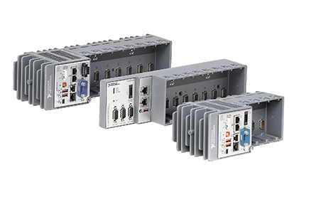
CompactRIO systems from NI fulfill all requirements for real-time signal processing for industrial monitoring and control applications, including long-term data acquisition. The chassis with user-programmable FPGA directly access the module circuits in order to implement time-critical applications for data acquisition, high-speed signal processing, control, timing or triggering directly in the hardware and react to them in real time. The sensor-specific I/O modules are used with dedicated software applications such as LabVIEW FPGA. CompactRIO controllers with Linux real-time operating system include a processor for highly reliable LabVIEW real-time applications. They enable multirate control, data logging and communication with peripheral devices.
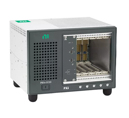
NI's PXI systems include powerful, modular measurement devices and input/output modules with specialized software and synchronization capabilities. The systems are particularly suitable for data acquisition and sensor measurement applications as well as other test applications with a high number of channels, for production tests in automated manufacturing and for device validation.
The USB-based multifunction I/O devices from NI enable high-quality measurements at an entry-level price. They can be used without modular hardware. The compact and lightweight form factor is ideal for benchtop measurements with your laptop or PC. The DAQExpress software included in the scope of supply offers an interactive approach so you can start measuring faster. For advanced measurement and automation applications, the supplied NI-DAQmx driver offers support for the programming languages ANSI C, Python, Visual C# .NET, Visual Basic .NET and LabVIEW. The driver supports all DAQ systems from NI.
For the optimum configuration of a data acquisition system for your test application, it is important to precisely define the demands of the application in good time. Answering a few key questions provides valuable information for the selection of the equipment.
You are not quite sure yet or have further questions about the products? Do not hesitate to contact us. Whether directly on the phone or via online demo conveniently in front of your screen - our experts are there for you.

